
 English
 русский
 فارسی
Our Fired heater for ADU and VDU is engineered for reliable and efficient heating of crude oil in both atmospheric and vacuum distillation processes. Designed for high thermal efficiency and uniform t...
See Details Home / News / Industry News / Industrial Manifold for Fired Heaters: Design, Selection, and Sourcing Guide

2026-11-20
Content
Picture a refinery engineer reviewing a radiant coil inspection report. Three tubes show bulging and heavy coking, while adjacent tubes look clean. The root cause is rarely the tubes themselves; it is often the inlet manifold that failed to split flow evenly. In fired heaters, a manifold is not a commodity pipe fitting. It is an engineered distribution header that sets the hydraulic and thermal boundary conditions for every tube downstream. Get the manifold specification wrong, and you will pay for it through shortened tube life, uneven coking, and unplanned decoking cycles.
The conclusion is straightforward: specify the manifold as a pressure part with defined flow tolerances, material certification, and weld quality requirements—then verify those requirements during fabrication. This guide explains what an industrial manifold does in a fired heater, why its design matters, and how to avoid common procurement mistakes.
In industrial heating, a manifold is a hollow header or block that collects or distributes process fluid across multiple branches. In a fired heater, you find inlet manifolds feeding radiant tubes, outlet manifolds collecting effluent, and intermediate manifolds in convection sections. The mathematical term “manifold” describes a topological space that locally resembles Euclidean space—useful in geometry but unrelated to the furnace component. This article focuses on the industrial manifold used in petrochemical, refining, and DRI furnaces.
| Aspect | Mathematical manifold | Industrial furnace manifold |
|---|---|---|
| Definition | Topological space locally resembling Euclidean space | Pressure-retaining header distributing process fluid to multiple tubes |
| Primary concern | Continuity, dimension, curvature | Flow distribution, pressure drop, thermal stress, code compliance |
| Typical materials | Abstract | Carbon steel, chrome-moly, stainless steel per ASME/ASTM |
| Failure mode | Not applicable | Erosion, thermal fatigue, weld cracking, maldistribution |
The manifold sets the flow split. If branch velocities vary by more than a few percent, tubes run at different temperatures. In a steam reformer, a 5% flow deviation can shift tube metal temperature by 15–20°C, accelerating creep. In an ethylene cracking furnace, maldistribution promotes coke in some passes while others under-coke. The practical consequences are shorter run lengths, higher decoking frequency, and reduced tube life.
Key design levers include header diameter versus branch diameter, inlet and outlet orientation, internal baffles or distributor plates, and thermal expansion flexibility. A well-designed manifold targets flow deviation within ±5% across branches at design turndown, with pressure drop low enough to avoid excessive pump duty but high enough to self-balance. Buying a “manifold” from a piping fabricator without flow analysis often results in field modifications, hot spots, and warranty disputes.
The manifold must match the tube material and design conditions. Specify ASME B31.3 or B31.1 as the piping code, and add NACE MR0175 if the service is sour. Require mill test certificates traceable to heat numbers, and confirm that welding procedures and welder qualifications cover the actual materials and thicknesses.
Provide the branch count, spacing, design flow rates, turndown ratio, and allowable pressure drop. Ask for a flow-network analysis or CFD study that shows branch-to-branch deviation. For critical reformers, request a physical or computational model that includes the inlet piping and tube sheet effects, because the manifold does not operate in isolation.
Decide between welded and flanged connections based on maintenance philosophy and leak risk. For welded manifolds, specify post-weld heat treatment where required, non-destructive examination (RT, UT, or PT), hardness testing, and dimensional reports. A manifold that arrives with weld maps, NDE records, and heat-treatment charts is easier to install and commission.
For an integrated supply, pair the manifold with the matching tube sheet and convection section module. This reduces interface risk and simplifies dimensional verification.
 Custom Stainless Steel Manifold for Fired-Heater SystemsUsed to collect or distribute process gas in reforming and cracking furnaces, with 347H, T91, 304L, and 316L options for thermal and corrosion conditions.View Product →
 Custom Cast Steel Tube Sheets for High-Temperature FurnacesHeat-resistant cast components for petrochemical, fertilizer, and power applications, with ZG40Cr25Ni20Si2 and Cr24Ni7 options for oxidation and carburization resistance.View Product →
In steam methane reforming, the inlet manifold distributes feed gas to reformer tubes, while the outlet manifold collects syngas. Thermal expansion and creep are critical; the manifold must accommodate tube growth without imposing bending stress on the catalyst tubes. In ethylene cracking, the manifold feeds feedstock to cracking coils, and coking plus decoking cycles demand robust design against thermal fatigue. In DRI, reformer tube assemblies rely on manifold headers to distribute process gas evenly across the catalyst bed.
Manifold design must integrate with the tube sheet, convection section, and firing strategy. A change in burner placement or coil outlet temperature can alter the required flow split, so the manifold specification should be revisited whenever the heater duty or operating envelope changes. For a deeper look at DRI reformer tube components, see this article on direct reduced iron technology and core equipment.
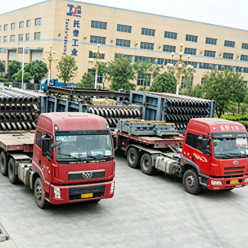 Custom Convection Section Module for Industrial Furnace Heat TransferModular convection and radiation heat-transfer component for petrochemical and chemical furnaces, designed for uniform temperature and lower fuel use; review alongside manifold design.View Product →
Common pitfalls include specifying the manifold by pipe size only, skipping flow analysis, accepting mismatched material, and allowing weld repairs without documented procedures. Missing post-weld heat treatment and inadequate NDE are frequent causes of early failures. Manifold welds often transition to radiation tubes; poor weld quality here can lead to premature tube failure. Review precautions for using radiation tubes before finalizing the connection details.
In fired heaters, the terms are often used interchangeably. A header usually refers to a larger collection or distribution pipe, while manifold emphasizes multiple branches. The functional requirement is the same: even flow distribution with acceptable pressure drop.
For most reformer and cracking services, ±5% branch-to-branch deviation at design and turndown is a reasonable starting point. Confirm with a flow-network analysis that includes inlet piping, tube sheet, and tube geometry.
Chrome-moly or stainless steel is common, depending on temperature and service. The manifold material should match the tube material or be metallurgically compatible to avoid dissimilar-weld issues.
Field fabrication is possible but risky. Shop fabrication with controlled welding, heat treatment, and NDE is preferred for pressure-retaining manifolds in critical service.
A manifold is a small fraction of the heater cost, but it controls the performance of the entire tube bank. The practical move is to treat it as an engineered pressure part: define flow tolerances, require material and weld documentation, and verify dimensional and NDE reports before shipment. That approach reduces the risk of hot spots, coking, and unplanned shutdowns—whether the heater is a steam reformer, an ethylene cracking furnace, or a DRI reformer.
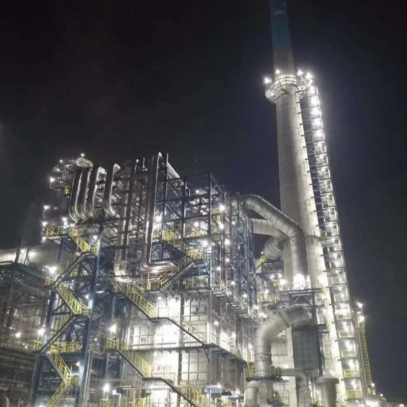
Our Fired heater for ADU and VDU is engineered for reliable and efficient heating of crude oil in both atmospheric and vacuum distillation processes. Designed for high thermal efficiency and uniform t...
See Details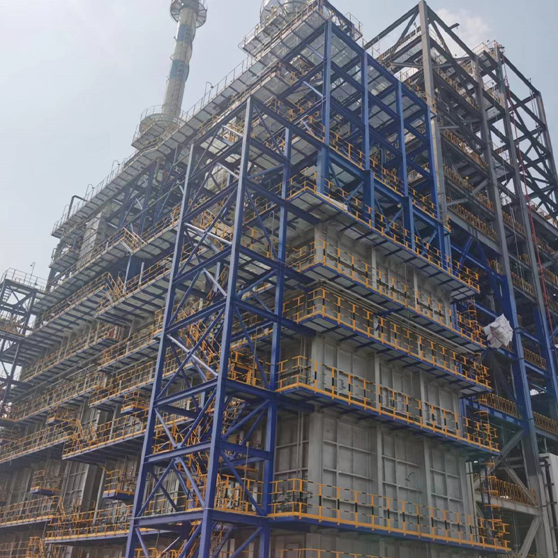
The Propane Dehydrogenation Furnace (PDH Furnace) is specifically engineered to provide stable, high-temperature heat for propane dehydrogenation processes in petrochemical plants. The furnace ensures...
See Details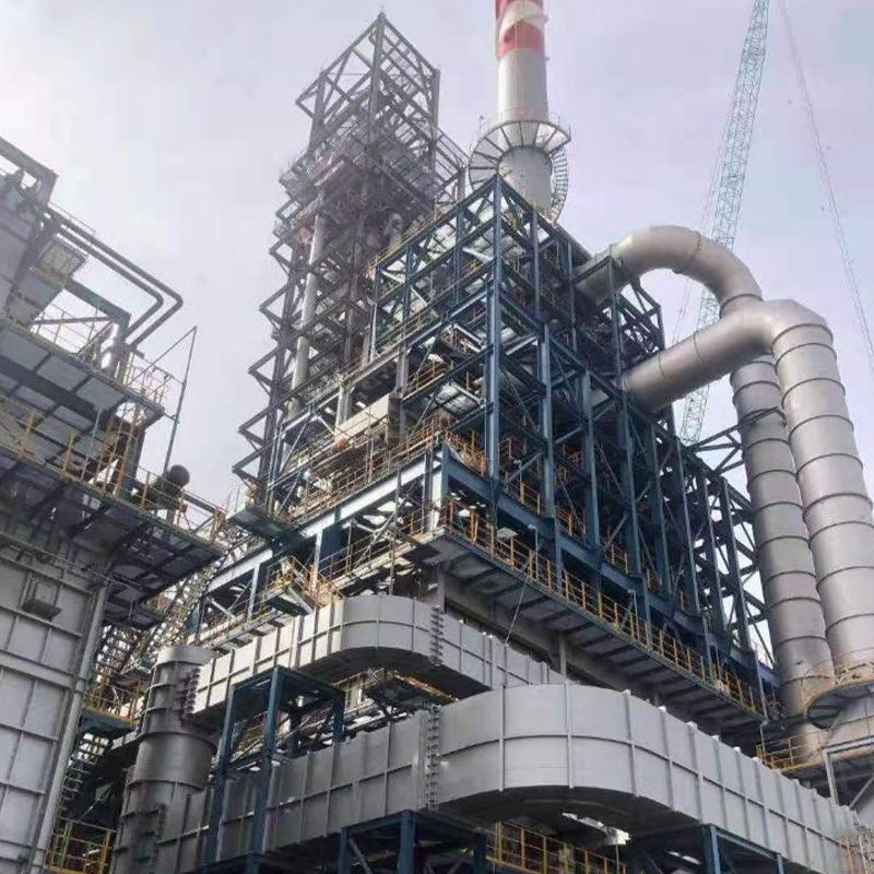
Our Four-in-One Reforming Fired Heater is a high-efficiency, advanced heating solution designed for modern petroleum refining and chemical processing operations. Engineered to optimize thermal perform...
See Details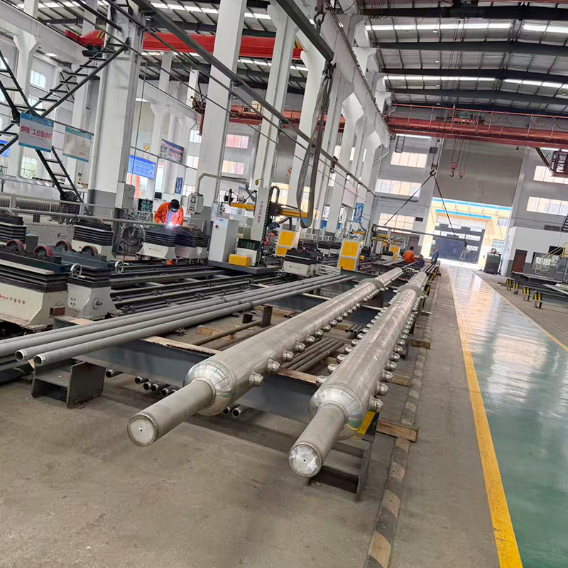
The outlet manifold collectors high-temperature converted gas (H₂+CO+CO ₂+CH ₄) from multiple radiation tubes, with a temperature of up to 700-900 °C, and needs to withstand thermal stress and hydroge...
See Details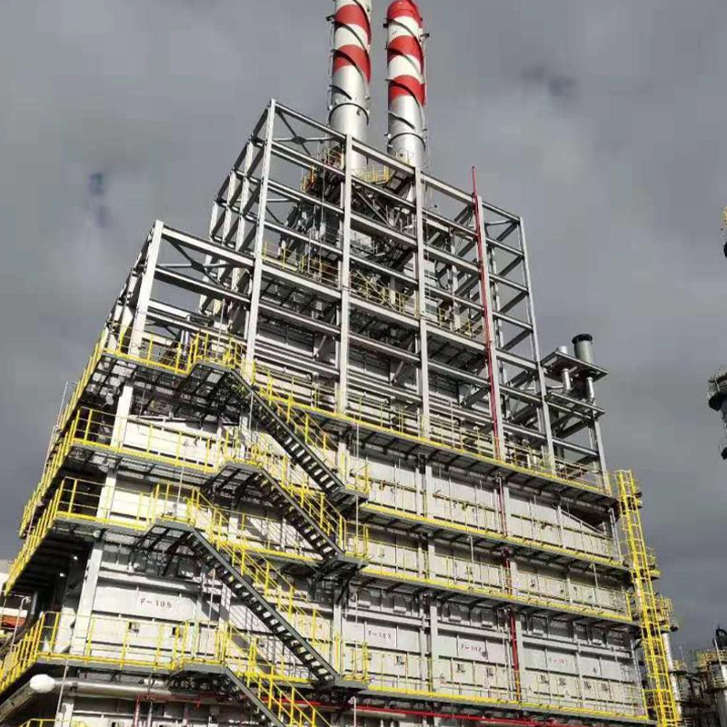
The furnace plays a critical role in maintaining high conversion rates, consistent product quality, and reliable long-term operation in petrochemical and chemical processing plants.By combining optimi...
See Details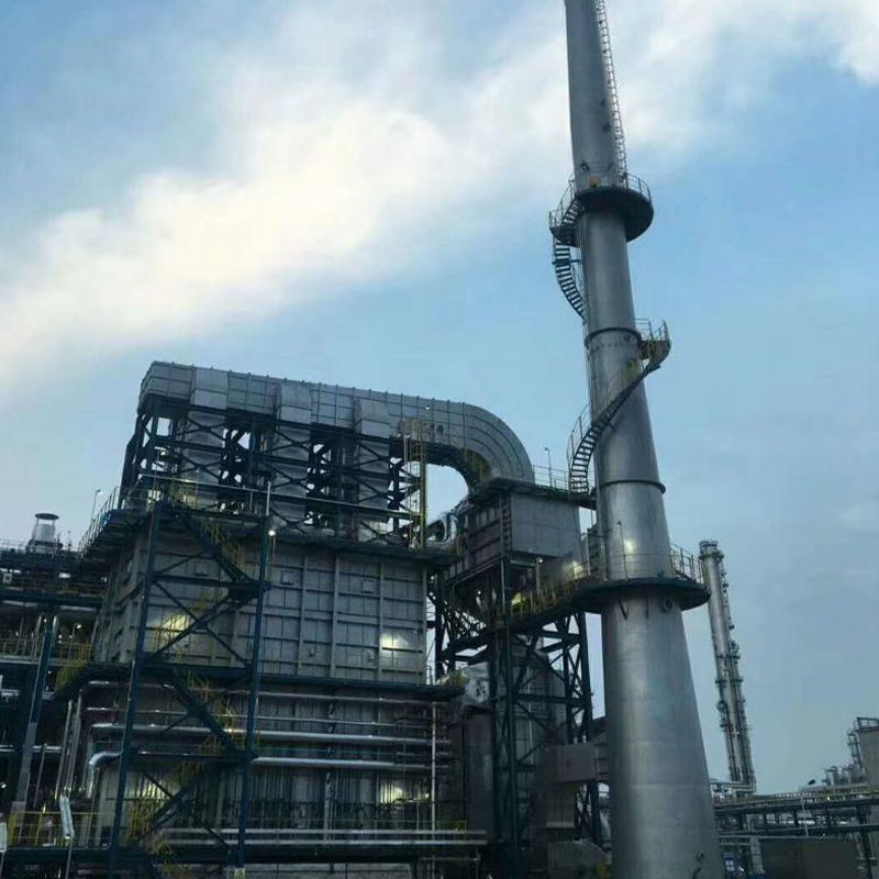
Used in various olefin conversion processes, the Olefin Conversion Fired Heater provides reliable and uniform heat input required for stable chemical reactions and process control. The furnace is desi...
See DetailsPhone
+86 189 5262 7611
+86-(0)523 8498 2299
Address
No.20, Fuyang Road, Jingjiang City, Jiangsu Province, China
Media