
 English
 русский
 فارسی
فارسی

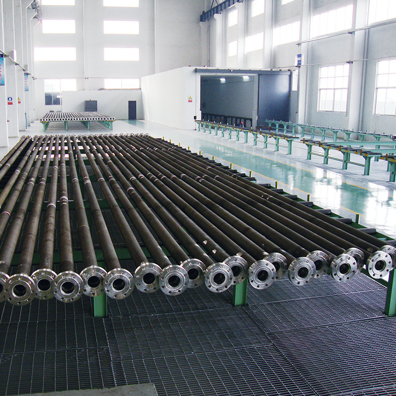
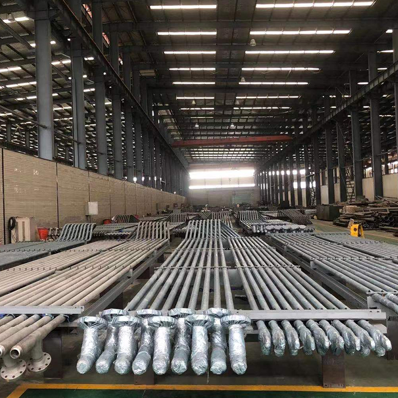
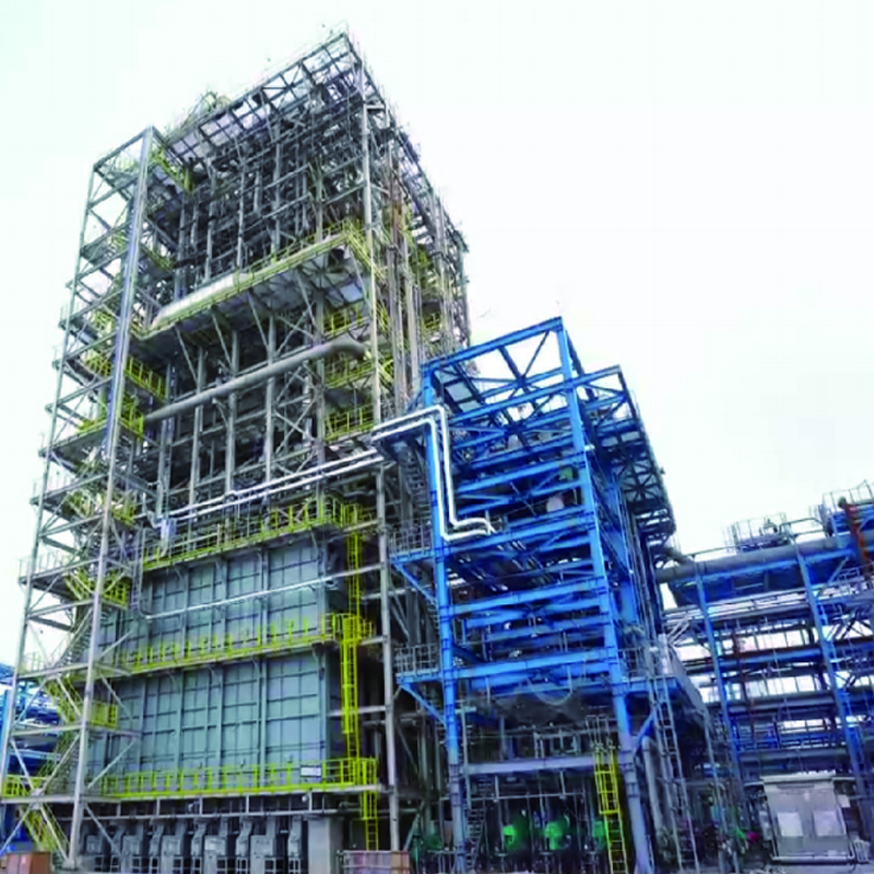
Tuopu’s DRI Furnace Tube Series is specially designed for Direct Reduced Iron (DRI) furnaces, offering superior heat resistance, mechanical strength, and long-term operational stability. Manufactured ...
See Details
2026-07-24
Content
The DRI industry refers to the segment of steel metallurgy dedicated to producing Direct Reduced Iron by converting iron ore into high-purity metallic iron through gas-based or coal-based reduction at temperatures below the melting point of iron. This process avoids the blast furnace route entirely, relying instead on reducing gas generated inside reformer systems to strip oxygen from iron ore pellets or lump ore. Equipment such as the DRI reformer tube, the shaft furnace body, and the associated fired heater network form the backbone of every DRI production line, and the reliability of these components determines both output quality and operating cost.
Gas-based shaft furnace processes account for roughly 75.8 percent of global DRI production capacity, with MIDREX and Energiron representing the two dominant technology licensors. The complete process chain runs through four connected stages: reduction inside the shaft furnace, gas reforming inside catalyst-filled reaction tubes, waste heat recovery through the convection section, and final briquetting or cooling. Because reducing gas quality drives the entire chain, the reformer tube network sits at the center of process performance.
| Process Type | Reductant | Reactor Form | Global Capacity Share | Typical Temperature |
| Gas-Based Shaft Furnace | Natural Gas / Hydrogen | Shaft Furnace | 75.8% | 900–1050°C |
| Coal-Based Rotary Kiln | Non-coking Coal | Rotary Kiln | 24% | 900–1050°C |
| Gas-Based Fluidized Bed | Natural Gas | Fluidized Bed Reactor | 0.2% | Approx. 600°C |
| Rotary Hearth Furnace | Coal / Coke | Rotary Hearth Furnace | Minor Share | 1250–1350°C |
Gas-based shaft furnace processes dominate the DRI industry because they combine high thermal efficiency with flexible output forms, including cold DRI, hot DRI, and hot briquetted iron. Reducing gas preparation is the operational core of this route: natural gas mixes with recycled furnace gas and flows through reformer tubes packed with nickel-based catalyst, producing a hydrogen-rich reaction stream that carries out the actual reduction inside the shaft furnace.
The DRI reformer tube is the pressure-bearing core of the reforming furnace, exposed to internal gas temperatures above 900°C, direct radiant heat from external burners, sustained internal pressure, and mechanical wear from the catalyst bed. A centrifugal casting furnace tube process is standard practice for this component because it produces a dense wall microstructure and refined grain structure, which translates directly into stronger creep resistance and oxidation resistance compared with static casting.
Material selection typically centers on high nickel-chromium heat-resistant alloys such as HP and HK grades, containing 25 to 35 percent chromium and 35 to 45 percent nickel, with niobium, tungsten, and titanium added for grain boundary strengthening. The same catalyst tube technology also supports the hydrogen generation reformer tube used in hydrogen production units, since both applications share nearly identical thermal and pressure demands.
Failure modes in reaction tube service mainly include creep deformation, thermal fatigue cracking, carburization embrittlement, and oxide scale spalling. These risks are addressed through controlled casting cooling rates, optimized alloy ratios, and rigorous inspection of every tube sheet, manifold, and collector connection before the assembly leaves the factory.
The following equipment lines cover the reformer tube network, the shaft furnace body, and related cracking and fired heater systems used across DRI plants, ethylene units, and refining operations.
A gas-based DRI shaft furnace is built as a refractory-lined cylindrical vessel. Iron ore pellets or lump ore charge from the top and descend by gravity, meeting the upward-flowing reducing gas in a counter-current pattern that completes the reduction reaction. Engineering for fired heater systems supporting this furnace must account for the height-to-diameter ratio of the shaft, uniform gas distribution across the cross section, controlled burden descent velocity, and a reliable dynamic sealing system at the charging and discharge points.
| Equipment Name | Function | Core Components | Application Field |
| DRI Furnace | Iron ore direct reduction reactor | Shaft body, refractory lining, gas distribution system | Gas-based DRI plants |
| Reformer Tube Assembly | Reducing gas reforming reactor | Reformer tubes, catalyst, tube sheet, pigtail tubes | DRI reforming systems |
| Ethylene Cracking Furnace | Hydrocarbon high-temperature cracking | Cracking tube, radiant section, convection section | Petrochemical ethylene plants |
| Hydrogen Generation Reformer | Natural gas steam reforming for hydrogen | Reformer tubes, burners, waste heat recovery | Refining and chemical hydrogen production |
Many of these systems share engineering logic with a fired heater for oil refinery service and a fired heater for petrochemical industry service, since all three rely on a radiant section, a convection section, and precise EPC for ethylene cracking furnace level coordination between furnace body design, tube metallurgy, and burner layout. Complete project delivery, from process design through installation and commissioning, keeps these interconnected furnace parts operating as a single reliable system.
The global DRI industry is moving toward lower-carbon operation. Conventional natural gas-based DRI already produces markedly lower CO2 emissions than the blast furnace route, and DRI technology built around 100 percent green hydrogen as the reducing agent is viewed as a leading pathway for steel sector decarbonization. Leading process licensors have developed plant configurations able to switch flexibly between natural gas, hydrogen, and syngas as reductants, keeping the door open for a full transition to hydrogen-based reduction without rebuilding the shaft furnace itself.
Plant scale flexibility is a second advantage of the DRI route. While a blast furnace and basic oxygen furnace combination typically needs an annual output near 2 million tons to remain economical, a DRI plant paired with an electric arc furnace can start operation from as little as 0.5 million tons per year. This makes the DRI industry particularly practical for regions with dispersed iron ore resources or limited natural gas and hydrogen supply, supporting mini-mill steelworks at a much smaller capital scale.
DRI reformer tubes are typically manufactured from high nickel-chromium heat-resistant alloys such as HP and HK grades using centrifugal casting technology, allowing them to withstand operating temperatures above 900°C and sustained internal gas pressure.
A DRI furnace is a shaft reactor built specifically for iron ore direct reduction, defined by counter-current gas-solid contact, a dynamic sealing system, and refractory lining. This differs fundamentally from a conventional fired heater in both process principle and structural design.
Reducing gas in gas-based DRI processes typically consists of around 55 percent hydrogen and 36 percent carbon monoxide, with an H2 to CO ratio near 1.5, generated through catalytic reforming of natural gas inside reformer tubes.
DRI is produced in three main forms: cold DRI, hot DRI, and hot briquetted iron. Hot briquetted iron is made by compressing hot DRI into dense briquettes for safer storage and transportation.
Under normal operating conditions, a reformer tube typically lasts approximately 8 to 12 years, depending on operating temperature, pressure fluctuation, catalyst replacement frequency, and the specific alloy grade used.
The DRI process consumes roughly half the energy of the blast furnace route and generates significantly lower CO2 emissions. When paired with 100 percent hydrogen as the reducing agent, near-zero carbon emissions become achievable, making it a core pathway for steel industry decarbonization.
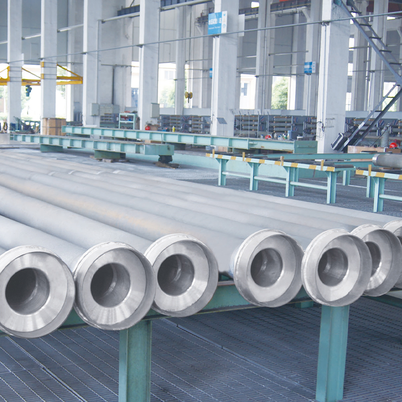
Tuopu’s DRI Furnace Tube Series is specially designed for Direct Reduced Iron (DRI) furnaces, offering superior heat resistance, mechanical strength, and long-term operational stability. Manufactured ...
See Details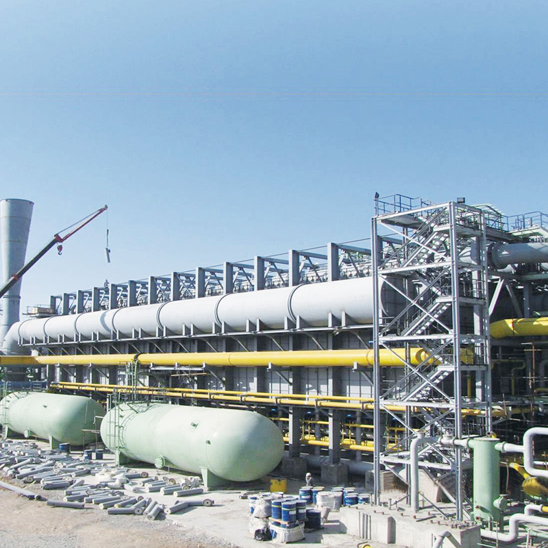
Tuopu’s DRI Furnace is a tailor-made solution designed specifically for steelmaking plants, providing reliable and efficient direct reduced iron (DRI) production. Engineered for high operational stabi...
See Details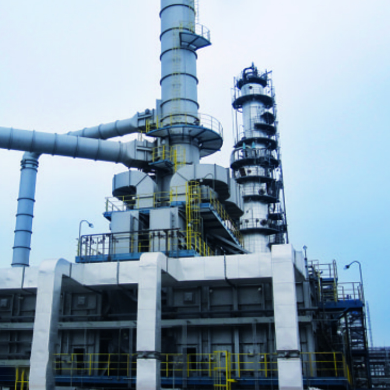
Our Heater for Visbreaking Unit is designed for efficient heating of heavy hydrocarbon feedstocks in viscosity reduction and cracking processes. By providing uniform, high-temperature heating, it ensu...
See DetailsPhone
+86 189 5262 7611
+86-(0)523 8498 2299
Address
No.20, Fuyang Road, Jingjiang City, Jiangsu Province, China
Media