
 English
 русский
 فارسی
فارسی
Our Fired heater for ADU and VDU is engineered for reliable and efficient heating of crude oil in both atmospheric and vacuum distillation processes. Designed for high thermal efficiency and uniform t...
See Details Home / News / Industry News / Engineering for Fired Heaters: Design, Tube Metallurgy and EPC Delivery
2026-10-09
Content
A vacuum distillation heater can pass its heat balance on paper and still bulge its tubes within two years. The duty figure was correct. What failed was a decision made in another discipline: a flux limit raised to save surface area, a burner spacing narrowed to fit the plot, a tube support moved to simplify fabrication.
So here is the short answer before the detail. Engineering for a fired heater is a coupling exercise, not a thermal calculation. Process duty, coil metallurgy, mechanical structure, combustion control and transport limits have to close together, because the weakest of them sets the maintenance interval.
When a heater is bought as a thermal rating with hardware attached, the gaps between disciplines reappear later as hot spots. Six engineering streams have to be developed in parallel, each producing information the others depend on.
| Stream | Typical deliverables | Failure mode if under-engineered |
|---|---|---|
| Process and thermal design | Heat balance, coil layout, flux profile, draft and flow calculations | Coking, hot spots, short coil life |
| Coil metallurgy and tube manufacturing | Alloy selection, centrifugal casting, weld procedures, dimensional tolerances | Creep rupture, carburisation, wall thinning |
| Mechanical, structural and refractory | Casing, supports, expansion joints, stack and duct steelwork, wind and seismic design | Cracking, leakage, vibration damage |
| Combustion and controls | Burner selection and spacing, air/fuel ratio, draft and temperature control, interlocks | Flame impingement, afterburn, unstable operation |
| Fabrication, inspection and QA | Welding, post-weld heat treatment, NDT, hydrostatic testing, dimensional control | Site rework, delayed start-up |
| Transport and erection | Modularisation, lifting points, roll-on/roll-off shipping, site assembly sequence | Damaged modules, idle cranes, schedule slip |
The sequence matters as much as the content: coil layout feeds mechanical design, and mechanical design feeds transport limits. On projects split across several contractors, the space between these streams is where problems live.
Duty sizes the heater; flux decides how long it lasts. Average radiant flux is the figure in the datasheet, but the tube that fails first sits in the peak flux zone, usually beside the burners or at the shield tubes where the radiant section begins.
Good practice keeps the peak-to-average ratio between roughly 1.3 and 2.0 depending on service, and holds the peak below a ceiling that is far lower for vacuum, coking and residue services than for clean, high-velocity streams. Coking rate and creep damage both rise sharply with tube-metal temperature, so a small local excess quietly consumes years of run length.
Mass velocity is the lever that lowers wall temperature without changing duty. Two coils with identical surface area can run at very different wall temperatures if their internal velocities differ, and the slower one usually looks cheaper on the quotation.
Our note on fired heater selection and engineering applications in the petrochemical industry covers that selection logic in more depth.
Alloy selection gets framed as a temperature question. It is also a carburisation, corrosion and weldability question.
Centrifugal casting gives reformer, cracking and radiant coil tubes a columnar grain structure with better creep resistance than static casting, which is why it dominates high-temperature service. Typical selections run from carbon steel and 1.25Cr–2.25Cr at moderate temperatures, through 9Cr–1Mo for hydroprocessing and steam reforming, to austenitic grades such as 347H and HP-modified alloys where metal temperatures exceed roughly 900 °C.
The details that decide whether the metallurgy survives are less visible: welding procedure and post-weld heat treatment for 9Cr material, tolerance on wall thickness and ovality, and bore cleanliness. A few percent of wall thickness variation changes both stress and heat transfer, and on catalyst-filled tubes it changes the pressure drop of the entire reactor.
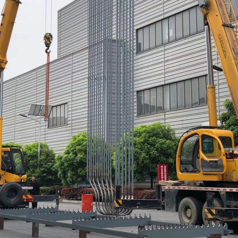 Custom Cracking Tube for Radiant Coil FurnacesReplacement radiant coil tube for high-temperature cracking furnaces; wall thickness, ovality, bore cleanliness and welding details influence stress, heat transfer and shutdown intervals.View Product →
On a cracking or radiant coil replacement, the tube is not an accessory to the heater. It is the component that defines the shutdown interval.
Refinery heaters look similar on elevation drawings and behave very differently in service.
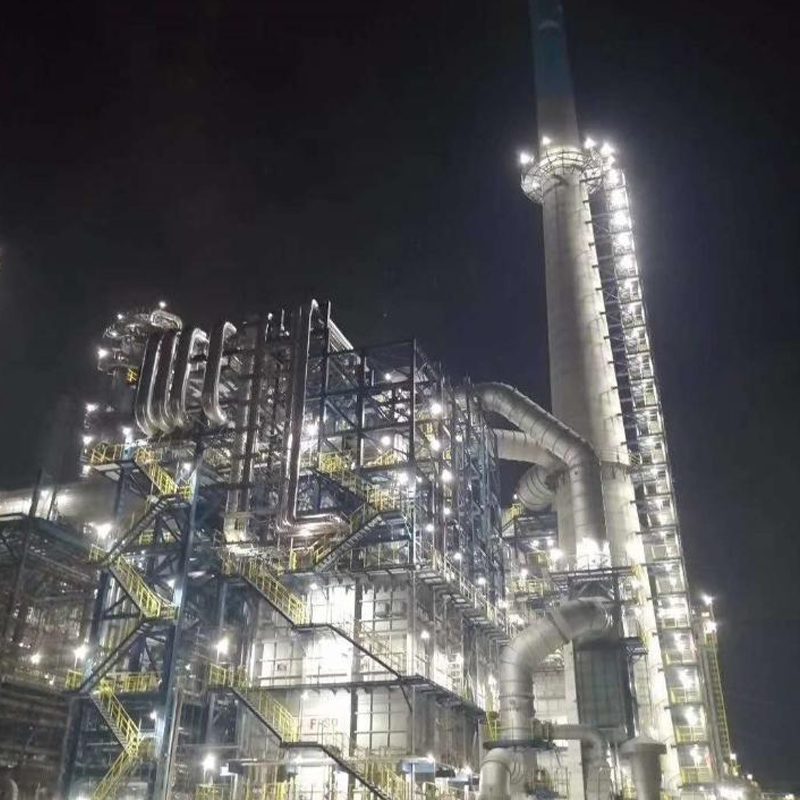 Custom Fired Heater for ADU and VDUEngineered for atmospheric and vacuum distillation, this fired heater offers uniform multi-zone heating, high thermal efficiency, and corrosion-resistant construction for refinery crude preheating.View Product →
In every case the process engineer sets the flux and velocity envelope, and the mechanical engineer has to deliver a coil that holds it without excessive pressure drop.
Chemical heaters push the same components harder. Ethylene cracking furnaces run coil outlet temperatures in the region of 800–870 °C with short residence times, which means high flux, high-alloy tubes and burner layouts that hold a uniform heat profile along the coil. Styrene units add a steam superheater, propane dehydrogenation and olefin conversion units need reaction heat delivered at a controlled profile, and hydrogen reformers depend on tube-wall temperature uniformity across the whole radiant box.
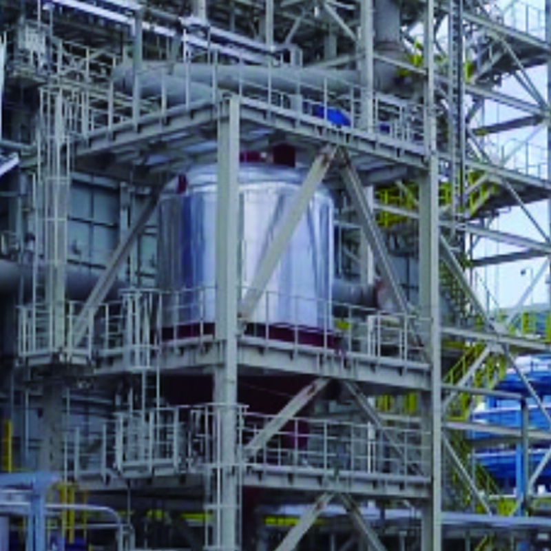 Custom Ethylene Cracking Furnace for Hydrocarbon PyrolysisFor ethylene production by steam cracking, featuring optimized radiant and convection sections and advanced burners for precise, uniform high-temperature heat.View Product →
The engineering lesson is that flux uniformity is a deliverable in its own right, demonstrated at the burner layout stage rather than discovered at commissioning.
Once the thermal design is fixed, three mechanical questions decide whether it survives in service.
Accessibility belongs on this list. If a tube cannot be replaced without cutting a structural member, the heater will cost more over twenty years than it saved at purchase.
The final engineering stage frequently decides the schedule. Radiant sections and convection modules are shop-fabricated as far as transport allows, which moves welding, post-weld heat treatment, non-destructive testing and hydrostatic testing into a controlled environment instead of a site compound.
Transport limits are genuine design constraints. A heavy equipment base of roughly 40,000 m² with a 20,000 m² assembly hall and 150 t lifting capacity sets the upper bound on module weight; a dedicated roll-on/roll-off wharf, about 200 m long with 8 m water depth and rated for 50,000 t roll-on movements, sets the upper bound on module size for overseas delivery. Those numbers belong in the mechanical design review, not in a shipping quotation issued three months later.
A heater that passed its performance test can still fail in its first year, and the causes are rarely exotic.
Figure 2: Illustrative split drawn from operating experience, offered as a prompt for review rather than a statistical claim. Burner tuning, oxygen trim and draft control account for the largest share of early problems, and all three are commissioning activities rather than design defects. Tube damage ranks second because it is where earlier compromises on flux, alloy and velocity finally appear. The practical response is a structured hot-spot survey in the first weeks of operation, repeated after the first planned shutdown.
Before releasing a fired heater order, get each of these answered in writing rather than in meeting notes.
No. Duty sets how much heat is transferred; flux and surface area decide the box size. Accepting a higher flux reduces surface area and cost up front, and normally shortens the run between decoking or tube replacement.
Whenever the process can deposit material on the tube wall, as in vacuum distillation, coking and residue services, or when outlet temperature sits close to the creep limit of the alloy. Clean, high-velocity streams tolerate higher peaks.
Enough that normal flux imbalance, a burner change and a modest feed variation cannot push tube-metal temperature past the design value. On a cast alloy tube, margin measured in tens of degrees is not conservative.
Flux profiles, velocity calculations, alloy and welding documentation, inspection records, and a transport plan checked against real lifting and shipping limits.
Engineering for a fired heater is not one calculation repeated at larger scale. It is a chain of decisions in which the thermal, metallurgical, mechanical and logistics answers must agree before fabrication starts, and where the cheapest option on any single link tends to reappear later as an operating cost.
If you are specifying a new heater, a coil replacement or a revamp, send our engineering team the duty, the service and the transport route, and we will tell you which link is likely to govern your project.

Our Fired heater for ADU and VDU is engineered for reliable and efficient heating of crude oil in both atmospheric and vacuum distillation processes. Designed for high thermal efficiency and uniform t...
See Details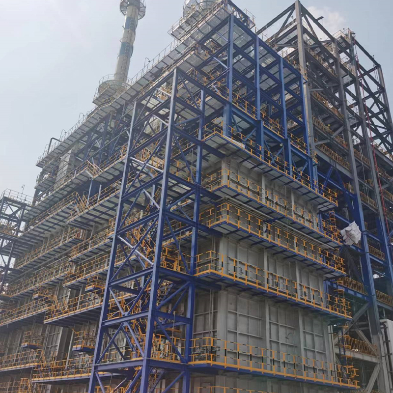
The Propane Dehydrogenation Furnace (PDH Furnace) is specifically engineered to provide stable, high-temperature heat for propane dehydrogenation processes in petrochemical plants. The furnace ensures...
See Details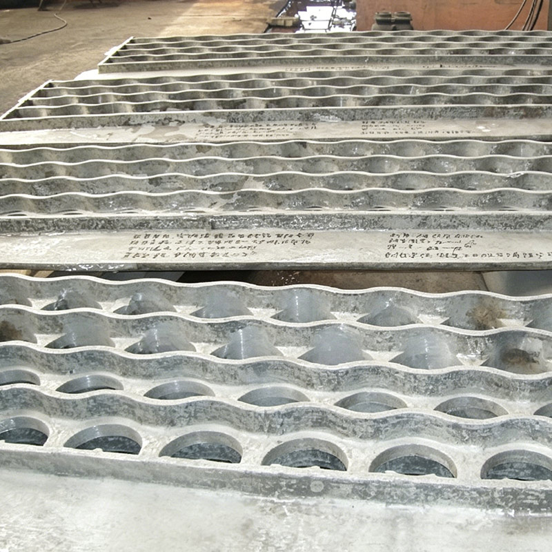
Cast tube sheets have good heat resistance and structural integrity, and are commonly used in industries such as petrochemicals, fertilizers, and power plant. It is recommended to use heat-resistant s...
See Details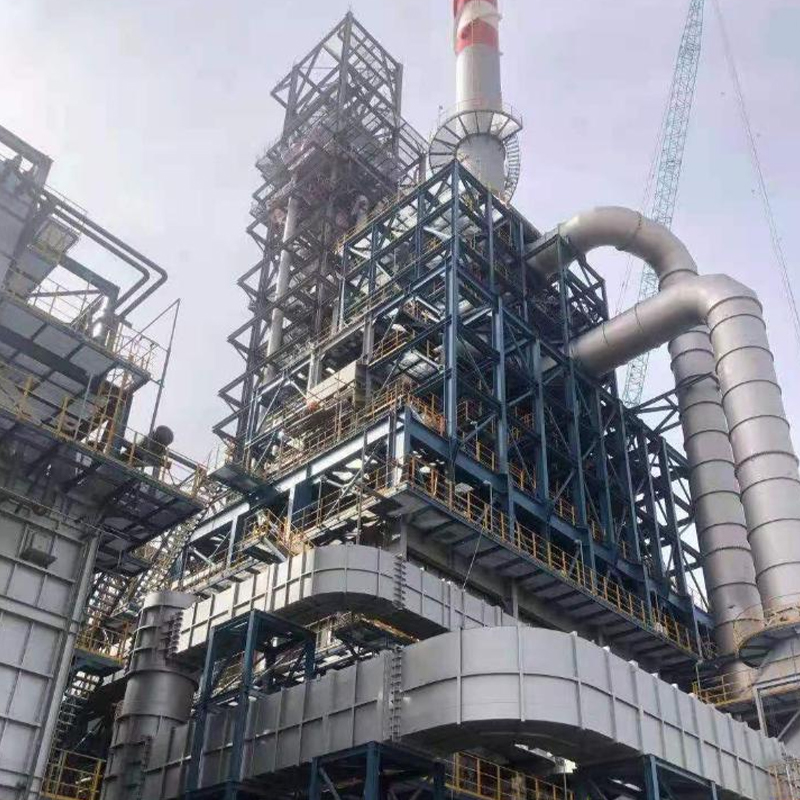
Our Four-in-One Reforming Fired Heater is a high-efficiency, advanced heating solution designed for modern petroleum refining and chemical processing operations. Engineered to optimize thermal perform...
See Details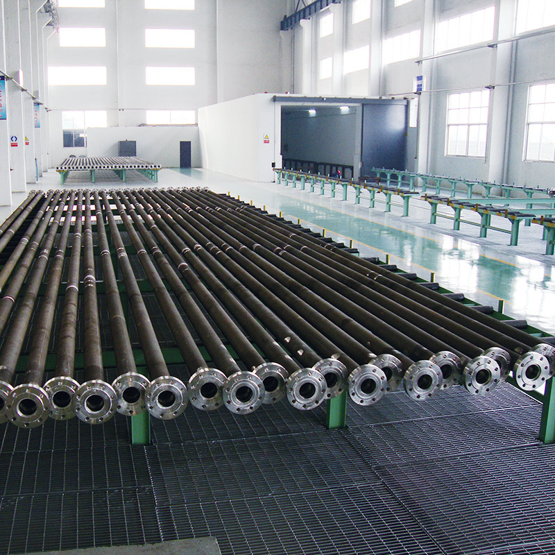
Tuopu’s Reformer Tube is designed for high-temperature chemical reactions in industrial furnaces, ensuring efficient heat transfer, structural integrity, and long-term operational stability. These tub...
See Details
Tuopu’s DRI Furnace Tube Series is specially designed for Direct Reduced Iron (DRI) furnaces, offering superior heat resistance, mechanical strength, and long-term operational stability. Manufactured ...
See DetailsPhone
+86 189 5262 7611
+86-(0)523 8498 2299
Address
No.20, Fuyang Road, Jingjiang City, Jiangsu Province, China
Media